Sunday, December 28, 2008

Kurukshetra CEG's Annual TechFest (21 st - 24 th january)

Kurukshetra is an Annual Tech Fest of College Of Engineering Guindy (CEG) ..Its a part of Anna University Chennai .Its one of the premier institutes in India .The best part there are prizes worth 10 million waiting to be bagged .

Kurukshetra
(21 st - 24 th january)

  • Designer's Quest
  • The Road Not Taken
  • Robotics - Line Follower
  • Robo Soccer
These are the four robotics event in kurukshetra 09 .

Robo Soccer is the easiest among these events and perfect for newbies .
Robotics - Line Follower lies in the intermediate category .
The Road Not Taken is based on image processing .Which is somewhat advanced .

There is also a special event for showing your creativity "Designer's Quest" . Where imagination is the limit .So participate in kurukshetra and win grand prizes .

Creating simple image using INTEL'S OPENCV

Hi Everyone
In future there are going to be no robots without a vision system .Computer vision is going to be a main and integral part of future robots .Even at present there are lots of robots using image processing to navigate and identify objects .

Now to explore this science MATLAB is a very good tool .But for real time applications and applications that are fast MATLAB is no good .MATLAB consumes a lot of your computers resources .

Now here I found a neat blog for tutorials on openCV . myopencv has tutorials at beginner levels .
Here I have tweaked one of his code to create an image with black and white striped pattern .Do look at the site for more information .Here is the source code for generating black and white striped pattern .

#include "cv.h"
#include "highgui.h"
#include "stdio.h"
int main()
{
/*Creates an image size 600 by 600 ,IPL_DEPTH _8U
means each data Element has a pixel depth 8 bits
1 means one channel*/
IplImage *img = cvCreateImage(cvSize(600, 600), IPL_DEPTH_8U, 1);

int i, j,k,l;
uchar *data;
data = (uchar *) img->imageData;//pointer to the Image data
/*consider a 2d array here, we go to the first horizontal line
process it and then we go to the next horizontal line.
The above for loop goes to the next line after a line is processed*/
for (i = 0; i < (img->width); i++)
{/*This for goes length wise(means it works horizontally on the Image.*/
for (j = 0; j < (img->height); j++)
{
for(k=0;k<5;k++){ one="255”" style="color: rgb(255, 0, 0);">data[i * (img->widthStep) + j * (img->nChannels)] = 255;
j++ ;
}
/*else assign zero, image should not contain garbage values it
is always good to force assignment*/
for(k=0;k<5;k++){ style="color: rgb(255, 102, 102);"> data[i * (img->widthStep) + j * (img->nChannels)] = 0;
j++ ;

}
}
}
/*This function creates an image with name ‘image’*/
cvNamedWindow("image", CV_WINDOW_AUTOSIZE);
//showing the image
cvShowImage("image", img);
/*saving the image parameters name with Extension*/
cvSaveImage("testimg for_prog.jpg", img);
//wait for any key and Exit
cvWaitKey(0);
//release img
cvReleaseImage(&img);
//destroy the window
cvDestroyWindow("image");
return (0);
}
The important lines ,I have highlighted in red .

Sunday, December 14, 2008

PIC16F877A EEPROM Tutorials

There is a inbuilt EEPROM in most of the PIC microcontroller series .PIC16F877A has 256 bytes of EEPROM inside it .So you can use it to store data that you might need on a permanent basis and you can read it back from it .The picture below shows the representation of the memory in the EEPROM .


For instance in the above picture I have entered 0x01 in the location 0x88 .
0x01 is the data and 0x88 is the address where the data is stored .I guess you
got the system .

Now let is look at the mikroc specifics of the EEPROM library .There are two functions in this library to accomplish the task

  • Eeprom_Read
  • Eeprom_Write

Eeprom_Read function returns an integer and takes a parameter of the address from which the data has to be fetched .The following is the syntax .

unsigned short Eeprom_Read(unsigned int address);

Eeprom_Write takes two parameters the first one is the address and the second one is the data .The syntax is given below .

void Eeprom_Write(unsigned int address, unsigned short data);

You can use these two functions to read and write data from the pic EEPROM .I will show you the actual working code in the next post .

Next Post ---->

Saturday, December 13, 2008

mikroc program pulse width modulation

<---Previous Tutorial

Now lets see how to write a code using the mikroc compiler to control the pwm module .
For your convenience MikroC provides PWM library and there are 4 functions present in

  • Pwm_Init
  • Pwm_Change_Duty
  • Pwm_Start
  • Pwm_Stop
The pwm_init takes a arguement of frequency in hertz

To Initialize a PWM module at 5KHz do this :Pwm_Init(5000);

Pwm_Start and Pwm_Stop are self explanatory I guess .These functions doesnt take any arguements .

Pwm_Change_Duty Changes PWM duty ratio. Parameter duty takes values from 0 to 255, where 0 is 0%, 127 is 50%, and 255 is 100% duty ratio. Other specific values for duty ratio can be calculated as (Percent*255)/100.

Take a look at the following simple program

void main (){
portb = 0x00 ; //clear portb
TRISB = 0xFF ; //Set PortB as input
PORTC = 0x00; // clear PORTC 
TRISC = 0; // PORTC is output
Pwm1_Init(5000); // Initialize PWM modulen set frequency as 5000
Pwm1_Start(); //Start the pwm module
while(1){
if (portb==0x80) //if rc7 is high
Pwm_Change_Duty(127); //set the duty cycle as 50%

}
}

This program creates a pwm on pin17 of PIC16F877A .

Hope you found this tutorial useful .If you have any doubts about the program .Leave a comment .

Friday, December 12, 2008

CCP Module in PIC16F877A -- Tutorial

<--Previous Tutorial Next Tutorial--->

In this post I will cover about the PWM module present in the pic microcontroller .I will cover it using PIC16F877A but it can be applied to any pic with a CCP module .

What's CCP module ?

CCP-- Capture Compare Pulse Width Module

Capture - The contents of the 16 bit timer,upon detecting an n th rising or falling edge, is
written to internal registers .
Compare - Generate an interrupt, or change on output pin, when Timer 1 matches a pre-set
comparison value .
PWM - Create a re-configurable steady duty cycle square wave output at a user set frequency.

For more information see this MicroChip pdf .

For now I am not going to cover the capture and compare modules .Lets see about the pwm module . You have 2 channels in PIC16F877A to accomplish the task .
Its present in pins

16 --- RC1 ---- CCP2
17 --- RC2 ---- CCP1
As you notice there are two channels present in the pic .This is ideal for robots with two wheel differential drive .You can achieve smooth turns acceleration if you use these two pins intelligently .Now let us see how to program the pwm using mikroc in the next tutorial .

<--Previous Tutorial Next Tutorial--->

Thursday, December 11, 2008

pwm pulse width modulation tutorials

There are a number of occasions where you might need Pulse Width Modulation for regulating power to a number of devices .It could be your Motor or even a lighting device .Let me explain
PWM first .

It is the variation of duty cycle from 0 to 100 % .To put it in a smiple way

"Pulse width modulation is the process of switching the power to a device on and off at a given frequency, with varying on and off times."

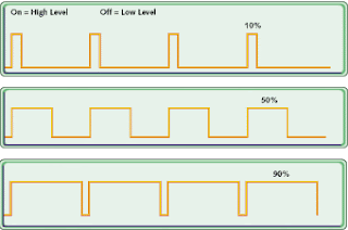
The following picture will give you a clear idea about it


It shows three different PWM's of 10% , 50% and 90% .
Notice: 100 % would become constant DC .

For instance take 10% duty cycle .You switch on the power for 10% of the time and switch it off for the remaining 90 % of the time .

Let me give you a practical example .Take a wave of frequency 1KHZ =1000 HZ .The time period of one wave as you know is 1millisecond .So a wave of 10% duty cycle will remain switched on for .1 millisecond
50% for .5 ms and so on .

You could achieve PWM by simple circuits like using a 555 timer .But the best part is you have built in pwm modules in PIC16f877A .Using which you can modulate the wave .For applications like motor control you can acheive smooth acceleration using these pwm modules present in the PIC .I will tell you about the coding and pic specifics in the next post .

Tuesday, December 9, 2008

Lead Acid battery Choosing For Final Year Project

Batteries are an integral part of robot design, as important as the frame, motor, and electronic brain. Batteries come in all sizes and shapes .So, an appropriate choice has to be made depending on the application .If the application demands high current and longer period of operation lead acid battery is a good choice. Although Lithium ion battery would be a ideal choice for our project it is very costly when compared with lead acid battery .Since our design can carry heavy weights we decided to use lead acid battery for its cheap availability even though it is heavy.

Lead acid Battery Types Usage

LEAD-ACID BATTERY

Lead Acid batteries were developed in the late 1800s, and were the first commercially practical batteries. They remain popular because they are easy and inexpensive to manufacture. Rechargeable lead-acid batteries have been available since the 1950s and have become the most widely used type of batteries today.

There are three main types of lead acid batteries.

Wet Cell (flooded)

Gel Cell,Absorbed

Glass Mat (AGM).


The Gel Cell and the AGM batteries are specialty batteries that typically cost twice as much as a premium wet cell. However they store very well and do not tend to sulphate or degrade as easily or as easily as wet cell. There is little chance of a hydrogen gas explosion or corrosion when using these batteries. Gel Cell batteries, which are best used in very deep cycle applications, still are being sold but AGM batteries are typically better. In most cases AGM batteries will give greater life span and greater cycle life than a wet cell battery.Why I choose Lead Acid for my project ,I've written in my next post .