There are a number of occasions where you might need Pulse Width Modulation for regulating power to a number of devices .It could be your Motor or even a lighting device .Let me explain
PWM first .
It is the variation of duty cycle from 0 to 100 % .To put it in a smiple way
"Pulse width modulation is the process of switching the power to a device on and off at a given frequency, with varying on and off times."
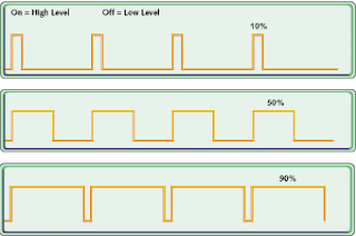
The following picture will give you a clear idea about it
It shows three different PWM's of 10% , 50% and 90% .
Notice: 100 % would become constant DC .
For instance take 10% duty cycle .You switch on the power for 10% of the time and switch it off for the remaining 90 % of the time .
Let me give you a practical example .Take a wave of frequency 1KHZ =1000 HZ .The time period of one wave as you know is 1millisecond .So a wave of 10% duty cycle will remain switched on for .1 millisecond
50% for .5 ms and so on .
You could achieve PWM by simple circuits like using a 555 timer .But the best part is you have built in pwm modules in PIC16f877A .Using which you can modulate the wave .For applications like motor control you can acheive smooth acceleration using these pwm modules present in the PIC .I will tell you about the coding and pic specifics in the next post .
Thursday, December 11, 2008
pwm pulse width modulation tutorials
Posted by
Arun Vijay
at
10:33 AM
Subscribe to:
Post Comments (Atom)
No comments:
Post a Comment